
NJDOT has provided 42Freeway.com a summary update on the Direct Connection Wall Rebuild efforts which have started, to fix the collapsed wall and roadway at the project in Bellmawr NJ.
I’d call this an “Executive Summary”. There are real details in this information such as what they are doing right now, the next steps, and the gameplan for the new rebuild.
To be clear though this isn’t a deep dive that answers all of our questions. But I still manage to turn a few sentences from NJDOT into pages of commentary!
As an example of information provided, for the rebuild they will be using a completely different design technique for the wall and foundations. The rebuilt wall will NOT be a Mechanically Stabilized Earth (MSE) system using pre-cast panels, as they did in the original effort.
Also, this new information does not include the cost of the repair and who pays for it… but it does overview how they plan on rebuilding and the timeline for this segment of elevated roadway to be completed.
NJDOT engineers call the wall (and roadway) segment where the collapse occurred “Wall 22”, and for ease of discussion I will use that going forward when referencing it.


Information breakdown related to the Direct Connection Wall Rebuild
Initial Wall collapse summaryNJDOT analysis reportInitial “Forward Plan” summary, including rebuild est completion(this article)- Detailed Forward Plan
- Rebuild costs and who pays
- Full project completion timeline
Thank you to the NJDOT Media team for providing this summary information, which I have subsequently greatly expanded on.
Direct Connection Wall/Road Collapse Bellmawr
If there is anyone out there who doesn’t know what this is all about…
The Direct Connection project is a $900+ Million Dollar project centered in Bellmawr New Jersey which intends to streamline roadway travel in this high traffic and confusing roadway area where Routes 295, 76 and 42 converge.
It is called “Direct Connection” because a key goal is to give the Rt 295 Federal Highway a more direct connection through the complex roadway area. Actually, they hope to give every possible path a more direct connection route to their destinations. (Direct Connection Explainer Post and Video)
As of April 2011 the project was expected to be completed in 2017 based in news articles. That was changed to 2021 based on a start year of 2013. The Philadelphia Inquirer has reported the latest full completion date is 2028.

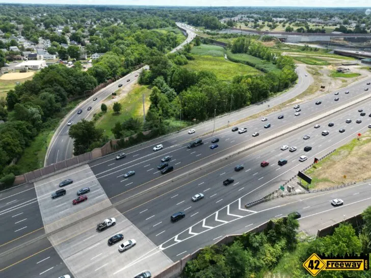
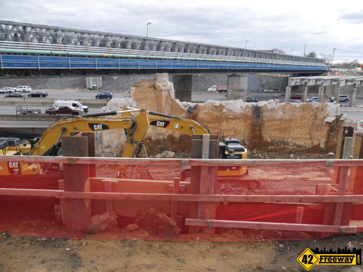
On March 25, 2021 a large segment of the not-opened-yet wall and roadway collapsed (Wall 22), with the tall retaining wall sliding out and away from the road, causing the roadway surface to fall in on itself. (Sinking analysis article and video)
In June of this year NJDOT released a very detailed report on the causes of the slide/collapse of Wall 22. It did not provide details on what the forward plan to correct would be (this was not part of its charter). (Cause report article and video)
This article today is to cover aspects of what that forward plan to correct Wall 22 is, including a rough timeline.
Note: There is a “sister” project called Missing Moves which will handle the road connections not covered by the Direct Connection project. (Missing Moves September 2022 Update)
All of my Road project coverage can be found here click here.
What is the Activity at the Site Now?
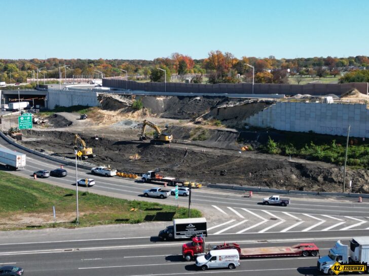
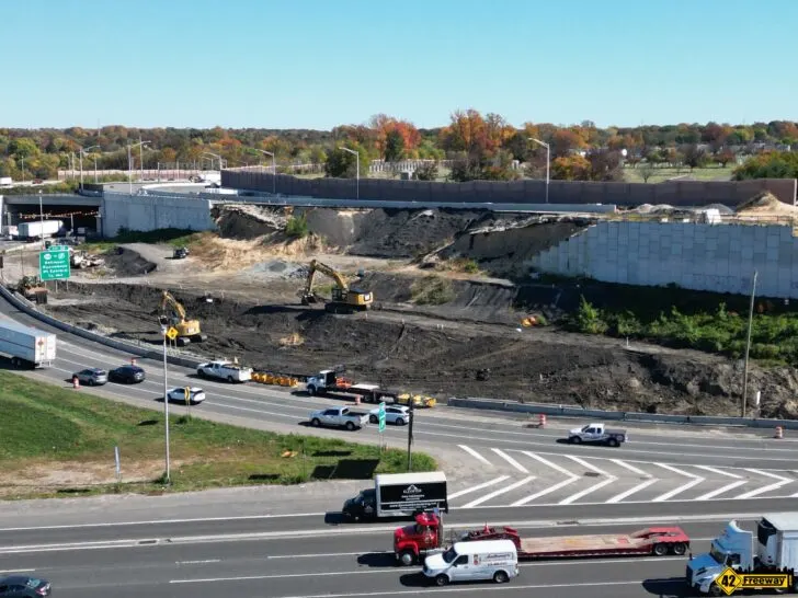
You may have noticed activity has been taking place at the base of Wall 22 recently, close to the 42/76 curved roadway where it heads off to the right.
Construction crews and heavy equipment have been onsite at the base of the project, clearing a work area and building a temporary raised earth foundation to support crews as they begin to work on the demolition and then rebuild of Wall 22.
For this aspect, NJDOT provides the following information
In preparation for the wall repair, the access road and shoulder were widened and repaved. This work was completed the weekend of October 15 and 16.
On Monday, October 17 the right shoulder was restored with construction barrier separating the shoulder from the work zone. In addition, drainage work behind the barrier was recently completed. The access road will mitigate lane closures and traffic impacts while the wall is rebuilt.
NJDOT Communications Team to 42Freeway.com
So simply crews onsite have currently been working to make a safe and stable environment for the team who will be demolishing Wall 22 and rebuilding.
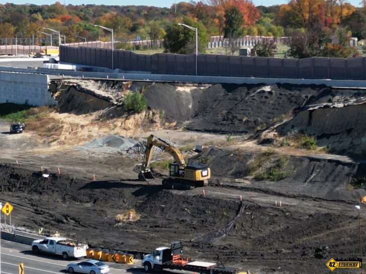
If you look at the drone image I took on October 27th (above), it seems they will have multiple levels in the work zone:
- Ground level (lower) area, level with the 42/76 roadway. This area is protected from the roadway by a barrier and extra drainage work was completed for this section. I’d imagine this is an area for workers to enter when starting their day, park vehicles.. etc.
- Raised work tier. This is where the center excavator is sitting in the image. This would seem to be were excavators can work from a stable base to cut into Wall 22 to remove the old structure and dirt. and then start the rebuild
Removal of Wall 22
Soon after the staging work area is ready, contractors will begin removing the wall.
NJDOT lists it as “in the coming months” and breaks it out into three facets
- Removal of remaining wall
- Excavation in preparation for the new wall.
- Clearing the site

An important aspect which is not defined yet is “How much of the wall and roadway is coming down, in terms of depth across the road surface and width (left and right)”
What I mean by this is… do they need to go as far back as to the area of the sound barrier wall at the cemetery?
And if you consider the full raised segment runs from the tunnel to the elevated column portion… well how much of that full curve has to come down?

A New Plan for the Wall Rebuild
Let’s start with the information provided by the NJDOT Communication on the rebuild.
The new wall utilizes a different design.
The original wall was a Mechanically Stabilized Earth (MSE) design in which precast concrete panels are held in place with horizontal reinforcing metal strips.
The new wall will be a cast-in-place reinforced concrete wall with Steel H-pile and drilled shaft deep foundations and a flatter slope. Additional drainage will be incorporated into the design.
NJDOT Communications Team to 42Freeway.com
Now watch as I turn 1 sentence into 20 pages of commentary!
That one sentence accounts for three key aspects of the wall; The wall construction, the foundation (two!), and the slope under the wall.
Wall: cast-in-place reinforced concrete wall:
Almost self-explanatory. The old project used individual concrete panels which were pre-casted off site, and metal horizontal strips embedded into the dirt would hold them in place.
The new Wall 22 will be poured on-site in larger sections (or section), not individual smaller panels.
So I’ll remind folks I am not an concrete engineer so I don’t want to go as far as to say that it’s one monolithic wall pour like the Hoover Dam. It could be, but maybe they need to add seams at intervals?
MSE is a very proven and successful means to build a highway retaining wall.
In the case of Direct Connection project though, the NJDOT Forensic Engineering reports states that the slope of the project caused issues with the full implementation.
Wall construction has stopped for several weeks in February 2019 because several of the panels were noticed to not be within contract compliance. Foundation material was an attributed cause.
The report goes on to say that subsequently 50% of the then partially completed Wall 22 had been reconstructed.
We’ll learn more over time.
A New Foundation for Success
A key aspect of the failure is attributed to the foundation system when the lateral pressures increased from the rain and slope, which allowed the earth under the wall to slide out.
In the Wall 22 rebuild there will be two main foundation technologies utilized which will be significantly stronger.
To clarify, by “foundation” this refers to; what extends down into the ground carrying the load of the raised earth, wall and roadway above… while also being strong enough to withstand lateral pressures. (Lateral, meaning side-to-side, which becomes more of an issue when developing on a slope)
In the new design they will be using both:
- Steel H-Pile: Strong steel beams where the “H” shaped configuration provides extra strength as the three planes support each other to resist lateral stress. They are pile-driven deep into the ground to stronger soil or rock below, transferring the load from above into those stronger lower layers.
- Drilled shaft foundations: A drilled deep hole which is then filled with reinforced concrete. There is a lot of flexibility in the width and depth of the resulting column. Similar to H-Pile, it transfers loads to the stronger soil or rock deeper below the surface.
Both are common and very successful ways to manage the weight of large projects AND higher lateral pressures which can come from an embankment installation.
More of those two concepts in a second.

Original Design: Poured unreinforced auger based columns
But first a step back, as I think it’s important to understand one of the key failure points of the original design (as described by NJDOT third-party analysis) and then interpreted by me!
The original design utilized a CSES (Column Supported Embankment System)
There were two components to the original design:
- LTM: Load Transfer Mats
- CMC: Unreinforced Controlled Modulus Columns
Envision it like the boardwalk at the Jersey shore where the boardwalk is comparable to the LTM horizontal mats, and it sits on top of columns which were driven into the sand.
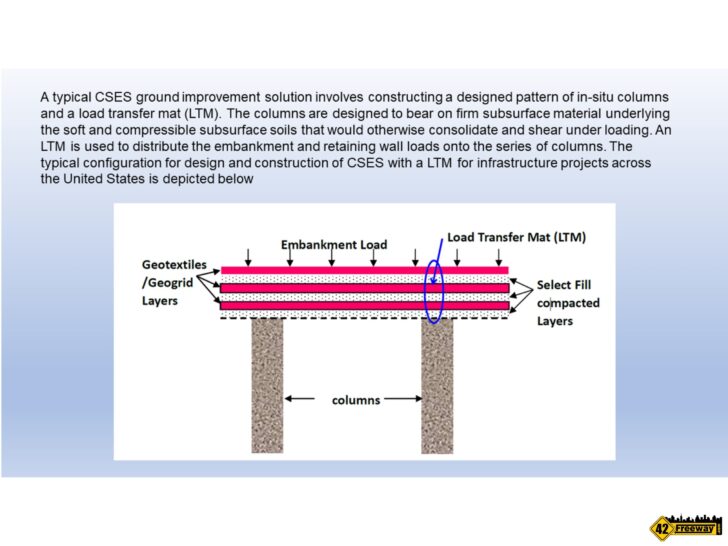
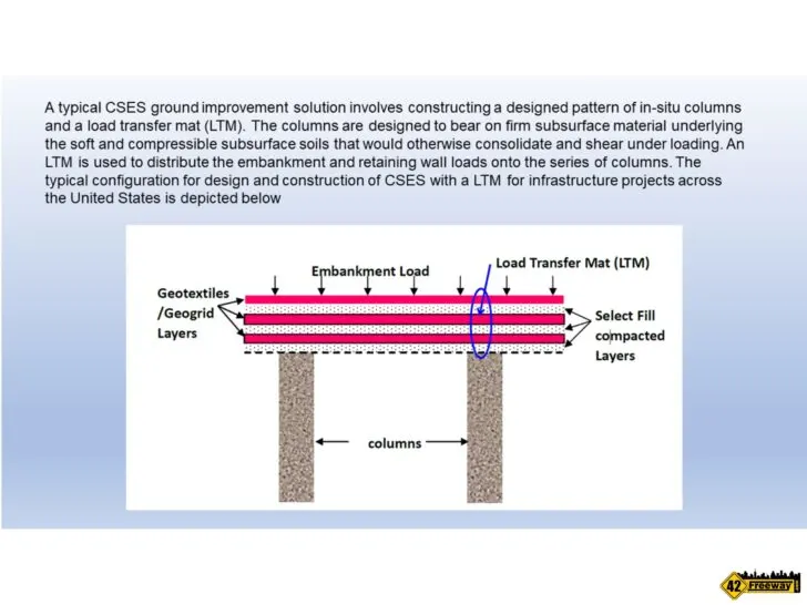
For the Direct Connection Wall 22 the general idea was that by positioning the mats underneath the raised roadway segments, the load from above would transfer into the horizontal mats first, and then be carried down deeper into the ground.
But in the direct connection project there was a big difference from my Jersey shore boardwalk comparison.
The columns used in Bellmawr were very long, poured concrete… unreinforced concrete.
Instead of drilling wide and deep holes and then pouring in high-strength reinforced concrete…
- they used a hollow tube auger to drill out a spiral threaded hole
- when it reached it’s lowest point they pumped concrete through the hollow tube and into the hole as it then backed out of the hole.
Add to that, the auger’s width was below original specifications. It was believed the auger threads would provide extra surface area to accommodate the thinner column width.
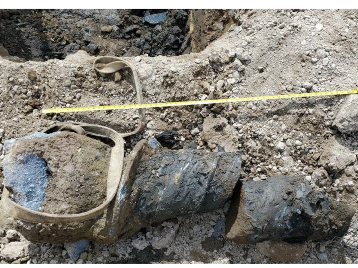

So by using unreinforced concrete the 70 foot long concrete columns did not have enough strength to handle horizontal pressures.
I imagine if the weight/load was always straight down it would’ve worked great!
But since they were on a slope, plus the introduction of water (from the rain) increased sideways pressure from the slope… causing those unreinforced concrete columns to fail, and the soil under the raised roadway surface and wall to slide out.
According to the findings of the NJDOT third-party engineering analysis, only 12% of the load was carried by the CMC Unreinforced concrete columns.
So simply when they rebuild Wall 22 it is crucial that they have a foundation system which can both transfer weight into the lower levels of the ground AND withstand larger lateral pressures.
New Design: More Rigid Deep Earth Foundations
As mentioned, the new design will utilize two different foundation technologies within the project.
Steel H-Pile and Deep Shaft Foundations both are long-term solutions to support heavy foundations and lateral stress.
Each of the two foundation concepts will be used in different parts of the Wall 22 rebuild, although at this time it has not been clarified.
Additionally, it seems it is possible to tie-together the exposed structures such as the new wall into the rigid foundation elements such as a steel H-pile. I am not clear at this time if that will be the case with the Wall 22 rebuild. In the original design the wall sat up above the foundation elements.
It is also possible to combine the two techniques by embedding the H-Pile into the a wider and deeper reinforced concrete deep shaft foundation. Also not clear at this point if the new Wall 22 design will incorporate that technique.
Steel H-Pile:
I am sure you’ve seen standard steel H-beams in television or print. When you look at them from the end the look like an H… and can be made very long.
The three planes of the H support each other from bending under stress, greatly increasing the strength.
There are obvious similarities to the beams used in a skyscrapers, which connected can be 1000 feet tall… except it seems foundation based steel H-beams like the ones expected to be used in the Wall 22 rebuild appear be more similar to an actual H with more equal depth and width.
Industry experts describe individual pieces of H-Pile as being tested to support over 1,000 TONS! That is a huge amount of weight.

There is a huge amount of information online regarding the use of H-pile steel in massive projects such as airports and bridges.
Pilebuck.com maintains an online series of articles regarding using piles in a variety of construction projects.
This article “Slope Stability and Protection” is very similar to the Bellmawr Direct Connection Wall 22 issue that occurred.
Their diagrams call out a “curved slipped surface” rotation risk, which is similar to what happened in Bellmawr as the soil underneath Wall 22 pushed under and out of the front of the slope.
There are ton of other more technical articles on H-piles and maintaining slope stability, but I like the simplicity of this line in the PileBuck.com article
Use steel H-piles for the abutment piling since steel H-piles are capable of taking large tensile stresses without failing.
Pilebuck.com
“Tensile stresses” is the resistances an object has to forces which can tear it apart.
In the case of the Direct Connection, those forces are lateral stress from being developed on a slope.
I’ll call out also the above quote is referring to “abutments”. Abutments are the vertical supports of a bridge which have special foundation concerns regarding supporting bridge weight and lateral stresses of slopes (consider a bridge going over a recessed river). While Wall 22 is not a bridge… it could be considered one elongated abutments
Drilled Shaft Foundations:
This will seem like a very logical concept.
Dig a deep hole, fill it up with very strong reinforced concrete. Done.
The simple concept is widely used in construction from bridge piers and abutments, and even including signage and roadside sign barriers.
The existing columns that we see at the Direct Connection project are likely continued into the ground via the exact same drilled shaft foundation.
Engineers have a lot of flexibility to drill shafts as wide as 10 feet across and over 300 feet down.
Effectively any size is possible, you just need a bigger auger.
So that is one difference from the original Wall 22 “CMC” columns… NJDOT engineers can design columns which are much wider than the ones in the original design, which would increase strength. Specifically lateral strength from pressures related to being on a slope.
The second huge factor is they typically would used reinforced concrete, which also significantly increases strength of the underground column.
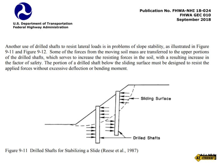
The US Department of Transportation has a course publication which perfectly shows the situation at the Direct Connection Wall 22 and how drilled shaft foundations are a viable engineering solution to support roadway construction on sloped land.
The diagram and commentary actually could apply to both steel h-pile and drilled shaft foundations
Another use of drilled shafts to resist lateral loads is in problems of slope stability. Some of the forces from the moving soil mass are transferred to the upper portions of the drilled shafts, which serves to increase the resisting forces in the soil, with a resulting increase in the factor of safety. The portion of a drilled shaft below the sliding surface must be designed to resist the applied forces without excessive deflection or bending moment.
US Department of Transportation Federal Highway Administration Publication FHWA-NHI 18-024
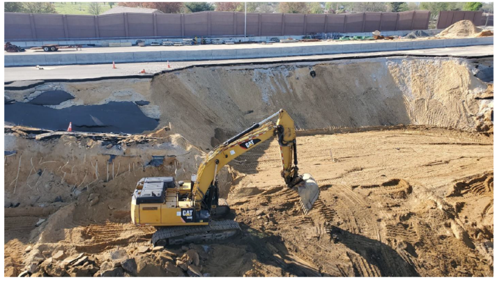
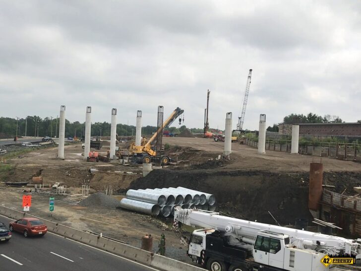
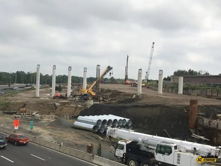
In my image above (from earlier in the Direct Connection project) you can see the tall concrete columns which then extend deep into the ground.
These were placed as bridge “abutments” to provide extra strength to attach the elevate roadway/bridges which will go over top of Browning Road.. The columns are now covered within the raised structure.
At minimum the rebuild of Wall 22 will utilize a deep drilled shaft foundation. What I don’t know is, will they also extend the tops of the columns up to the roadway surface. (not saying they need to)
Flatter slope and Drainage
A “flatter slope“… not as steep.
The original Wall 22 was developed at the top of a somewhat steep and tall slope.
I had called this out in my own analysis 18 months ago where I stated the tall and steep slope did not provide enough natural reverse force to push back on the pressures from the sloped weight of the Wall 22 filled earth, roadway and wall.
I gave an example from my own experience of installing a hot tub along the back of the outside wall of our old house. The local construction officials were concerned then that with the hollow lower basement on the other side of that exterior wall, would there ot be enough resistance to support the hot tub from collapsing into the basement!? Same principal at play.

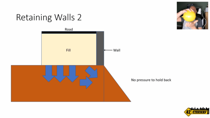
So while I imagine the foundation elements discussed earlier are the core mechanisms to support the load of the roadway and wall above, having a flatter slope should also increase lateral strength for the raised Wall 22, as the project area picks up natural resistance from the surrounding earth.
Drainage: Water from rain and also just naturally collecting at the site was a factor in causing lateral pressure to increase, causing the slope to slip.
The foundation elements described above will significantly strengthen the resistance from those stresses (and solve the concern). But water does need still have proper drainage.
While details were not given at this time, NJDOT does say they will improve drainage.
Timeline Impacts
The information provided by NJDOT closes with:
Construction of the new wall is expected to be completed in late 2024. We have not yet closed the loop on funding. While the wall is being rebuilt, other aspects of the project are continuing to advance, such as the Browning Road Bridge replacement. The entire project is expected to be complete in 2027.
NJDOT Communications Team to 42Freeway.com
Links and Location
Have have numerous articles and videos on the South Jersey based road projects including Direct Connection, Missing Moves and others.
Browse my “Road coverage” at 42Freeway.com via this link.