
The New Jersey Department of Transportation has made available to us the engineering analysis report which explains the factors which contributed to the Direct Connection wall collapse 14 months ago.
This web post is a summary, but the core of this 42Freeway report is a video walkthrough of the key aspects. Link is at the bottom.
Highlights of the official report findings include;
- sand was used for the slope and underneath the wall construction, and not adequate to support the load.
- underground concrete columns designed to support load were not adequate to support the weight/loads from above
- high groundwater conditions existed that were not fully accounted for in design phases
- heavy rain exacerbated the water conditions at the project area the night before.
The report was developed by engineering firm Hardesty and Hanover. 42Freeway is reporting on details from that report.
Hardesty and Hanover (H & H) are not part of the Direct Connection project, and they were hired for this reason to give an unbiased third-party analysis.
I know everyone wants to know:
- When will this be completed?
- How will they fix it?
- How much will this collapse cost to fix?
- Who pays for it?
But this report does NOT answer those questions.
It is focused on “Why did the roadway and wall collapse“.
Before the NJDOT can finalize the plans for how to correct the situation, they first needed understand all of the circumstances which caused the collapse.
Learn from your mistakes so you don’t repeat them!
That being said, there are some recommendations for improvements. Where a perceived deficiency was identified the report might say “had they used this type of column instead…” but that is not an official new design aspect.

The full package of information is massive… thousands of pages… but the first report is about 100 pages of commentary, diagrams and photos.
In their analysis, Hardesty and Hanover recreated all of the initial design and modeling scenarios with the original parameters, then determined how conditions actually varied on the project site.. and re-ran the tests all over again.
So the bulk of the provided documentation also includes all of the lower level testing details and outputs.
Overall it is a very thorough report which in some ways reads like a good detective novel… starts the novel with the core problem and then breaks it down into the details of how we got to where we are… a collapsed roadway.
We very recently put up a post and video on the progress of the Missing Moves project which is also located in Bellmawr.
Project Background
The Direct Connection project is a $900+ Million Dollar project centered in Bellmawr New Jersey which intends to streamline roadway travel in this high traffic and confusing roadway area where Routes 295, 76 and 42 converge.
While many problems are being addressed with the Direct Connection project, we feel that two key goals are
- Route 295 in this area is to be redeveloped with a more direct and straighter roadway which supports safer driving at consistent highway speeds. Currently there is a sharp bend in this area “Al Jo’s Curve” which requires traffic to slow down considerably, and creates a high accident area.
- The current blend of several highways mixing into a common large roadway, and then splitting off into multiple directions will be modified to have more direct “Point A to Point B” connections. More direct roads reduces lane shifting and traffic slowdowns.
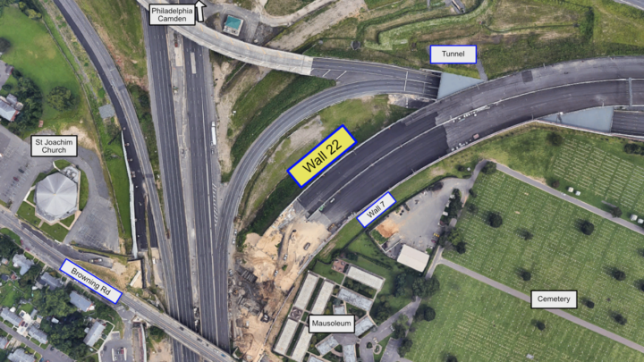

As mentioned the project is centered in Bellmawr New Jersey and primarily sits below the local streets in recessed roadways. The new design will bring the Route 295 portion up and over Browning Road in Bellmawr.
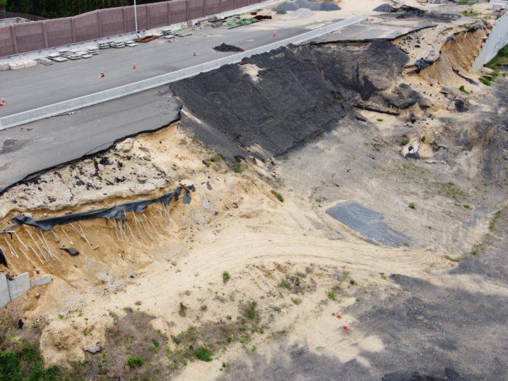
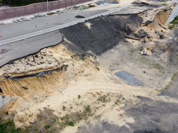
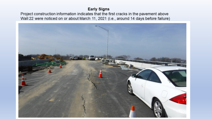
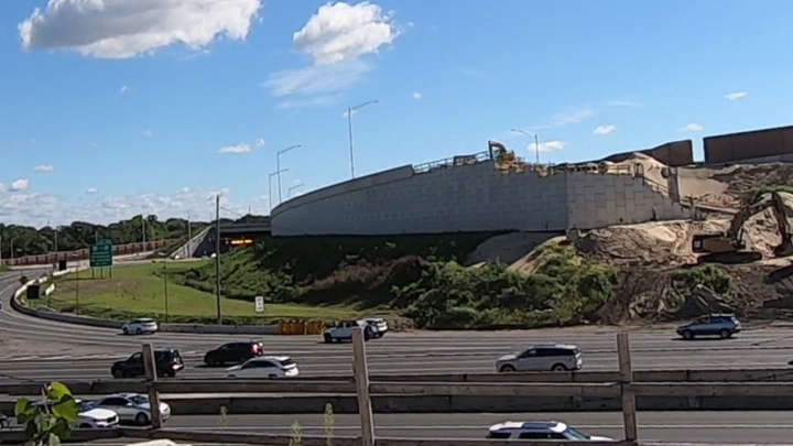
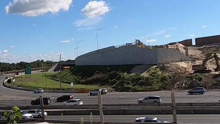
The Collapse happened on March 25, 2021 in a core portion of what will be the new 295 Southbound segment through Bellmawr.
At the time the roadway was not open, and there were no cars on the roadway.
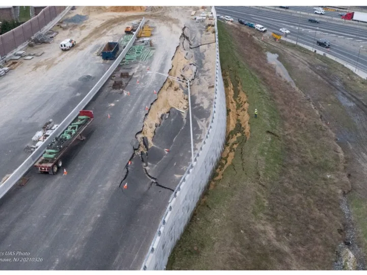
Heavy rain took place the night before and through much of the week. That morning of the 25th, commuters on the lower level Route 76 were surprised to see that mostly completed segment of the new Route 295 raised roadway had slid and collapsed.

Executive Summary
The H&H report opens with an executive summary of 4 key aspects they chose to highlight, and then “dig deeper” into the details.
The actual model of the report is to present the findings in logical sections with a core aspect being to split the raised roadway structure into three areas; The Wall, the lower sand slope, and the underground support systems. More on that shortly.
The highlighted Executive summary presents 4 key findings:
1) The I-11 (sand) material used for the embankment and slope was not an appropriate material to support a 30-foot-high retaining wall due to its poor engineering properties at high moisture contents.
2) The CSES unreinforced concrete columns were not adequate to withstand the vertical and horizontal loads from the elevated roadway embankment, I-11 slope, and the MSE Wall to provide a suitable safe foundation.
3) The project site has a known chronic high groundwater condition and showed previous indications of instability.
4) The heavy precipitation observed on March 24, 2021, appears to have exacerbated the groundwater conditions affecting the already marginally stable slope and ground improvement foundation system on which the wall was supported.
42Freeway also would like to highlight these additional elements from the report
For those who are only going to read the beginning of this post, I’ll call out some other details from the report which are mostly just addendums to the original 4.
1) Per contract plans, the wall was not detailed to extend down to the top of ground improvement LTM due to cost. (A variation on the first bullet above)
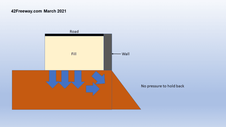
2) The vertical load-bearing aspects had sand AND an exposed slope in the middle. The exposed slope allowed load pressure to escape through the front slope of the project.
3) Groundwater was not taken in to account for some calculations.
4) It appears the MSE elevated wall was designed and performed properly. It was the foundation below it that failed.
Wall Deconstruction
Almost immediately after the wall collapse the project team (including H&H) were on site to deconstruct the collapsed area.
There were multiple goals in this aspect.
One was to further secure the site to reduce the chances of additional roadway slides.
They needed to make the area navigable for investigation and construction crews.
Additionally, they wanted to see into the lower levels of the fill and berm to identify failure points.

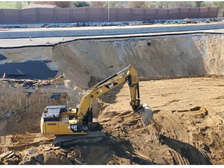
H&H was specifically looking to locate and document any failures with the MSE wall structure above, as well as the lower CSES underground support structures
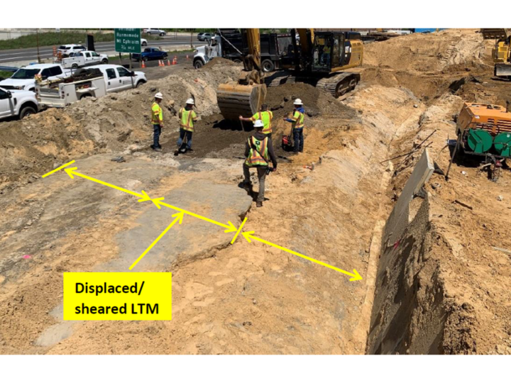
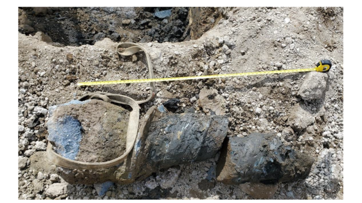
As mentioned, during this phase the teams did uncover shearing and displacement of both the LTM and CMC components (Described in more detail below)


(Hardesty and Hanover and NJDOT)
Wall Area Review
A technical review of the construction scheme, site history and subsurface conditions applicable to Wall 22 area was performed as part of the forensic assessment.
The report notes that there are 4 contracts to this large project.
We are currently in Contract 3, which includes the MSE Wall, fill and raised roadway bed.
Contract 2 was completed previously and some aspects of the project in contract 2 did have some impact on the larger roadway failure.
Contract 2: Cutting the lower slope. Clay enters the picture
The contract called for the initial removal of soil ahead of the roadway construction.
The area below the wall and slope were excavated lower than the final surface areas, per the contract specifications.
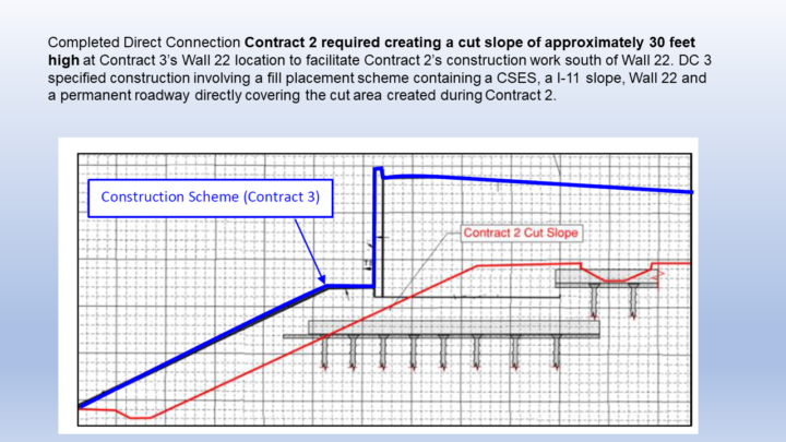
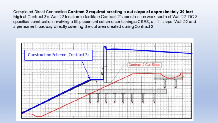
In Contract 3 these grades would be built back up.
The H&H document calls out that this exposed lower soil types, particularly more impermeable clay were now accessible ahead of the build up in Contract 3.
As mentioned the slope area and the area under the wall was built back up with sand.
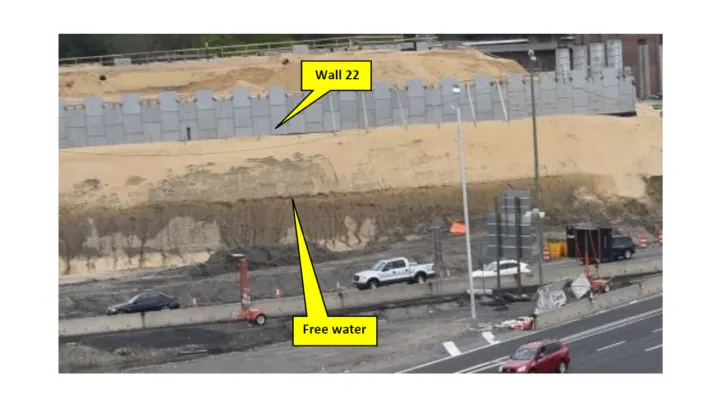
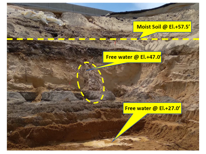
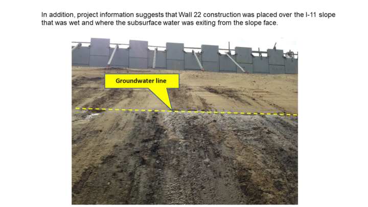
Higher Groundwater Conditions
This Contract 2 excavation created a situation where the clay stopped the groundwater from going lower into the ground, and the water followed down the more permeable sand and through the slope… at levels higher than anticipated.
Some aspects of the design phases (CSES) utilized a ground water level of +30 feet when during the investigation ground water was observed as high as +44 feet.
Higher water content in soil reduces strength.

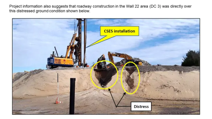
It was noted in the report that even during the early phases of Contract 2…even before the wall and fill above were created… there were notable incidents of embankment slippages and exposed water on the slope!
A fair amount of the report centers around groundwater.

(Hardesty and Hanover / NJDOT)
The report describes the confluence of these factors as “generally resulted in an unstable subsurface site condition”
Other points called out were that the groundwater seeping through the wall was seen at much higher levels than previously expected.

(Hardesty and Hanover / NJDOT)
Three Key Sections to the Roadway
The report breaks the analysis down into logical sections, highlighting the goal of each aspect, the analysis, whether the design and construction performed adequately, and lastly identified failures and successes.
In some cases where deficiencies were identified they offer suggestions, but these suggestions are not the “new plan”
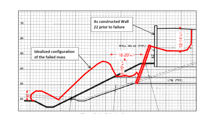
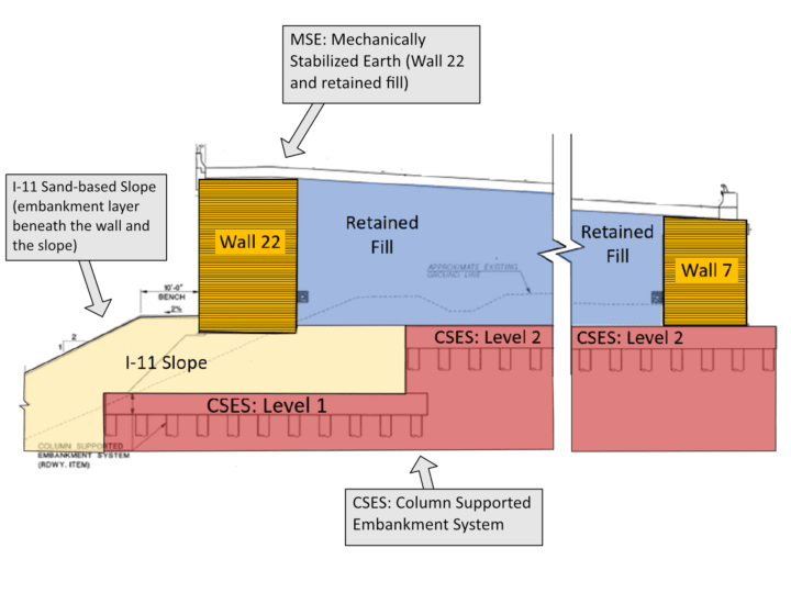
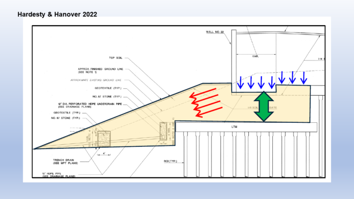
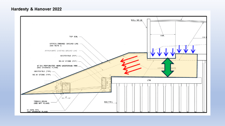
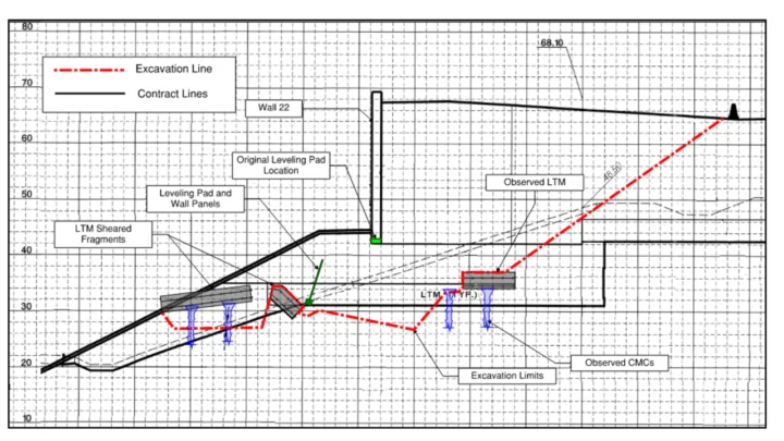
A cross section of the collapse area is presented, and they highlight three distinct areas to review. (there are other facets which are also delved into)

(Hardesty and Hanover / NJDOT)
Three key sections of the project area:
- MSE: Mechanically Stabilized Earth (Wall 22 and retained fill)
- I-11 Sand-based Slope (embankment layer beneath the wall and the slope)
- CSES: Column Supported Embankment System
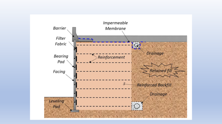
MSE: Mechanically Stabilized Earth
This is the core raised wall panel system, and was one of the most visually striking aspects for commuters below when looking at the collapse.
The findings do not seem to find fault with this portion of the project.
It was designed and developed to meet the project needs. The issues are with the constructed surfaces below it.
An MSE wall is basically a retaining wall to hold back fill… earth.
The walls today are engineered with rigid concrete wall panels with steel reinforcement elements going into the soil.
In a way its a reciprocal support mechanism. The wall is holding back the dirt, while the dirt helps hold up the wall!
(Hardesty and Hanover / NJDOT)
Drainage is a big consideration in the design, so the fill that is utilized must allow water through, and typically there are drainage pipes in key areas to collect and move the water out of the way.
This drainage requirement was a key reason for the use of sand as part of the project fill.
It is noted in the report that back in February of 2019 there were some early issues with the construction of the MSE panels, causing a work stoppage for a few weeks. The issue was identified, resolved.. and given full acceptance/approval by the project engineers. While called out in the report, this aspect does not seem to then be identified as a factor in the collapse.
I-11 Sand-based Slope (embankment layer beneath the wall and the slope)
The large slope which had angled away and down from the front of the wall, as well as an area going under the wall… was sand-based.
The large and heavy wall, as well as a good portion of the fill behind the wall… rested on the sand.
One of the reasons listed for using sand was to account for any groundwater in the project site, to facilitate drainage through the embankment.
Unfortunately H & H concluded that sand used in the project was not an adequate base to handle the load, factoring in higher levels of ground water and the sand was not contained.
As noted in a prior section, Contract 2 carved out a portion of the ground and the slope was developed on top of it. This is called out by H&H as an unstable ground condition for the slope to be built on!
Since the slope was sand based, with the addition of higher ground water on the project site it caused the soil to have a reduced strength with water seeping out at higher levels

(Hardesty and Hanover / NJDOT)
It is important to note that it was expected that for the large wall (as well as the fill material behind it), the load of that weight would be carried down through the sand and into the lower level CSES system…. which used horizontal mats and underground columns to support the weight.
The report identifies this as a “two-layer soil system” approach where as long as the soil is constrained on all sides to prevent horizontal movement, the soil would support the weight.
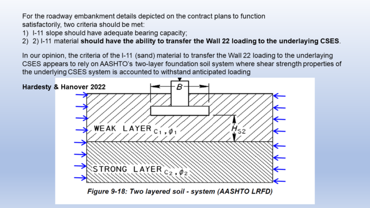
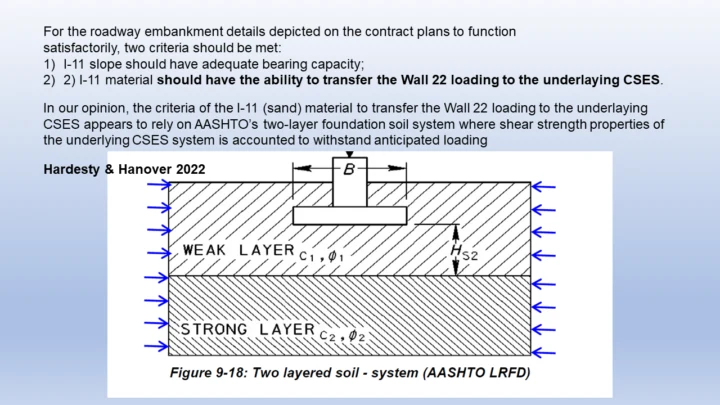
As an example, consider if you tried to stand on a pile of marbles. The marble pile would quickly collapse and roll out from underneath. Put those same marbles in a bucket where the sides prevent lateral movement, and now you could stand on them.
In the case of the Wall 22 collapse, the slope side of the sand fill had no restrictions in movement. As pressure built up above, and groundwater raised higher… the sand was able to slide out in front of the wall.
Incidentally this was a theory that Mark from 42Freeway put out over a year ago, soon after the collapse.
(Hardesty and Hanover / NJDOT)

The report calls out that additional test scenarios could have been run during the design phases to account for conditions at the site.
Interesting to note that the use of sand in a project like this is not necessarily a bad idea, but the slope did not properly contain the sand from lateral movement, causing issues.
CSES: Column Supported Embankment System
Early on project designers realized that developing a solid base to carry the load of the project above it was a key element of the design.
A CSES system was developed which is comprised of two components:
- LTM: Load Transfer Mats
- CMC: Unreinforced Controlled Modulus Columns
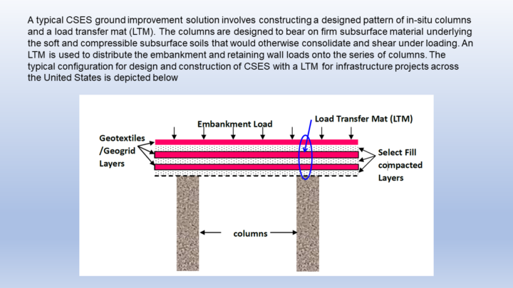
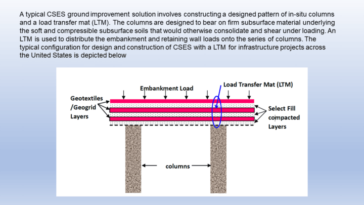
The CSES sits below the wall, backfill, and the portion of the sand that is also bearing the load of the wall structure above it.
The LTM is comprised of horizontal geosynthetic mats which area laid across a broad area under the project, to capture the weight/load above it.
The CMC are columns which are spaced out below the LTM to a depth of maybe 70 feet. The load picked up by the LTM is meant to be transferred to the CMC (columns below it), which was created much deeper into the surface.
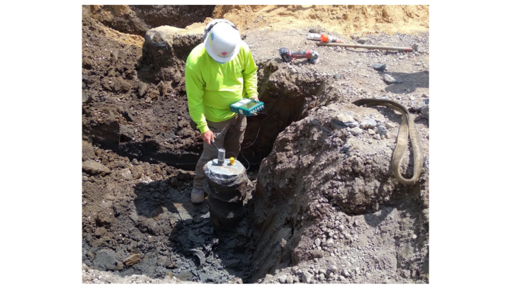
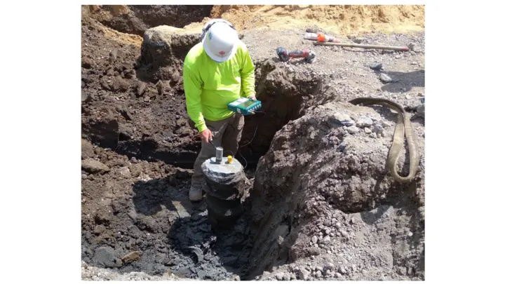
The CMC Columns were created on site by using a 12-inch auger to first drill down to depth.
The auger was hollow in the middle, which allowed concrete grout to be injected into the newly made hole.
The concrete columns were not reinforced.

(Hardesty and Hanover / NJDOT)
The H&H documents describe the diameter of column used was smaller than the original specifications, but by having threads in the hole and concrete column, it created more surface area. This change was approved.
During the Wall Deconstruction phase described below, the project teams were able to uncover shearing and displacement of both the LTM and CMC components.
The report does state that the CSES would satisfactorily perform if the I-11 (sand)slope is stable, but then it continues on to say that the CSES design submission failed to consider site specific subsurface soil conditions, elevated groundwater conditions and the strength reduction factor for plain concrete elements with no reinforcement.
According to the findings, only 12% of the load was carried by the CMC Unreinforced concrete columns.
It was noted in the report that a steel pipe column suggests the FOS (Factor of Slope Stability) of the CSES would increase significantly.

What’s Next?
Well it was great to get this report, but what’s next?
Seems we are back in the hands of the NJDOT and the Commissioner to provide us more updates.
I understand that the design teams have already started working on what the new Wall 22 structure will be, but it’s not complete nor available.
Maybe another OPRA request to come!
YouTube Video
I had just swore that I was going to cap videos at 7 minutes.
Then this report comes along days later… with a TON of information.
My first version was over an hour long. After editing and uploading, I deleted it.
So after about 12 hours straight of sitting at the computer, I decided to film it again at 11:30pm.
So I look tired and not as lively. Maybe not my best video effort but I got it down to 28 minutes.
Click this link to view in YouTube page or watch it embedded below